
Welcome to my first Jurassic Part build log! Seeing as this is my first build log I’ll begin with a brief introduction. Over the last couple years I’ve been learning Autodesk Inventor, a 3D CAD package. Now that I have a firm understanding of the software I can finally begin designing some of the projects I’ve had in my head for years. I’m also passionate about 3D printing and electronics, both of which will play a role in the project. I decided to start with a relatively simple project, the lock from the first Jurassic Park.

The front of the lock was simple enough, but I wanted to have a controllable door lock which makes this more challenging. In the next picture you’ll see a back view of the entire assembly. I have the locking mechanism selected so to highlight it. This makes it easer to distinguish from the body of the main lock frame. There are three fingers to the lock held by a single bracket on the end of the lock. They slide in a channel and have two rails that will hopefully keep them straight. There will be a thin sheet of metal on the back to provide a solid back that is easy to remove. It will just have holes drilled for the 6 bolts along the top and bottom of the main lock frame.
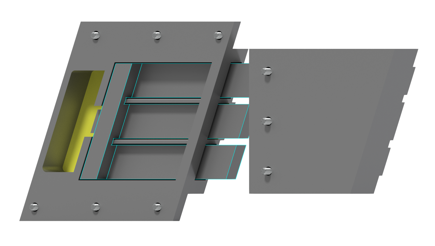
We now have the three main parts to our lock. The magic happens in the large lock frame so we’ll hide the locking mechanism and focus on that. The blue, yellow and black colors are simply to improve visibility during the design process. We’ll get into more detail on this view in a bit.

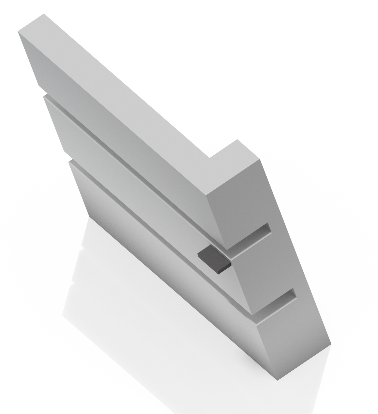
Next up we have a detailed view of the locking mechanism. Here you can see the small steel plate that will be used in conjunction with the electromagnets in the main lock frame.
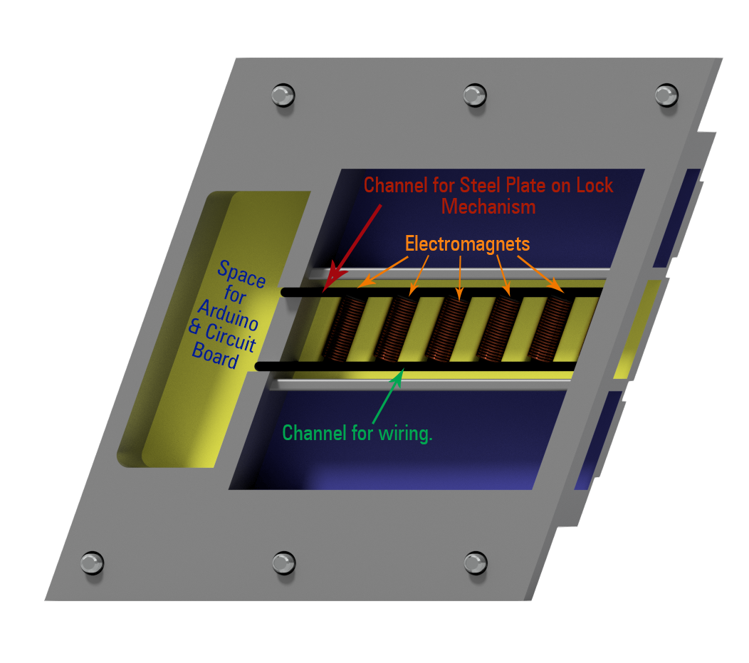
Now we begin the fun part! Trying to get all the parts to fit in such a tight space was quite a challenge and even now it’s still a concept at this point in time. The theory is that I will power up the electromagnets in a series to pull the locking mechanisim either forward or backwards. As the electromagnets get charged they should attact the steel plate on the locking mechanisim to their position. By charging these in order they should be able to pull the entire locking mechanism along the channel.
What’s Next?
Part 2: In part 2, I will 3D print main parts for this project. This part will include any sanding and final prep of the parts to make them look great.
Part 3: Design of circuit board – testing electronics to prove out concept.
Part 4: If all goes well with part 3, then this part will involve assembling the final pcb. If part 3 goes badly… well we’re back the the drawing board.
![Sorna Short Film Series [Fanmade]](https://jurassic.report/wp-content/uploads/2024/01/screenshot-2024-01-14-163951.png?w=1024)


Leave a comment